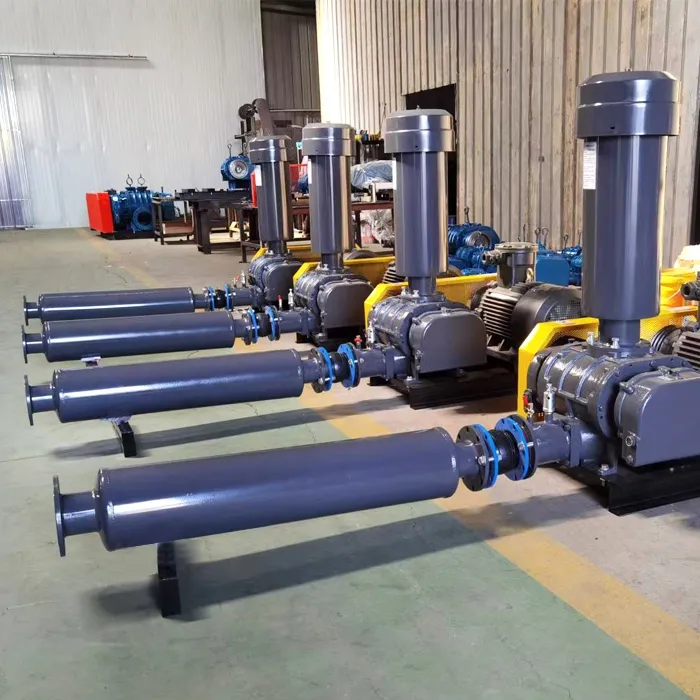
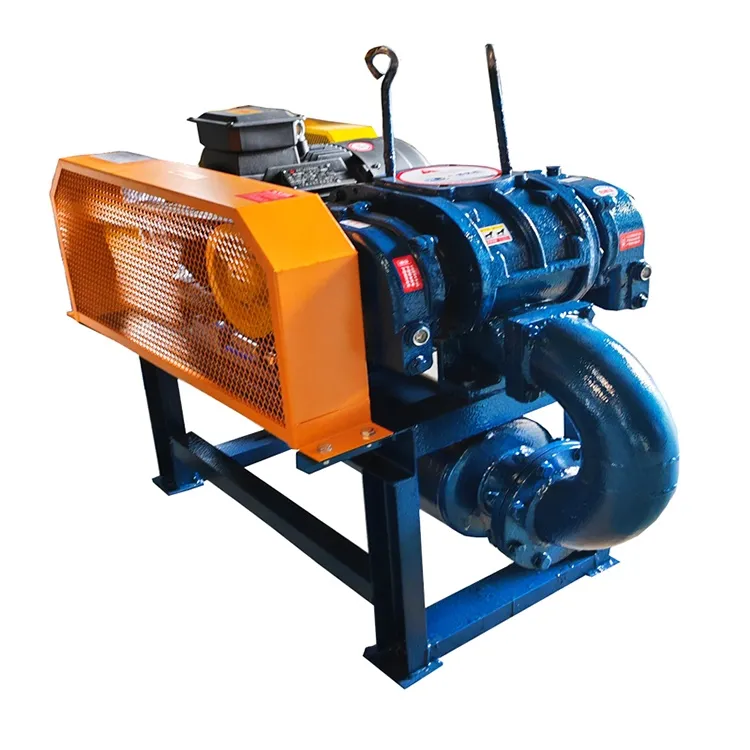
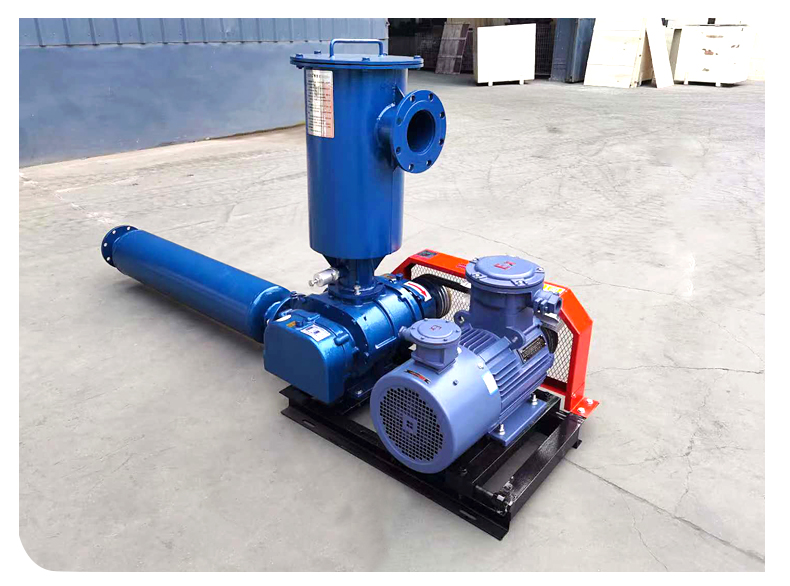
As a typical volumetric gas conveying equipment, the operating characteristics of Roots blower stem from its unique design structure (consisting of two three or two bladed rotors rotating synchronously in the opposite direction inside the cylinder). The following provides a detailed analysis of its operational characteristics from the dimensions of working principle, performance parameters, operational stability, maintenance requirements, and typical application scenarios:
1、 Core operating characteristics
- Forced gas transmission with constant flow rate
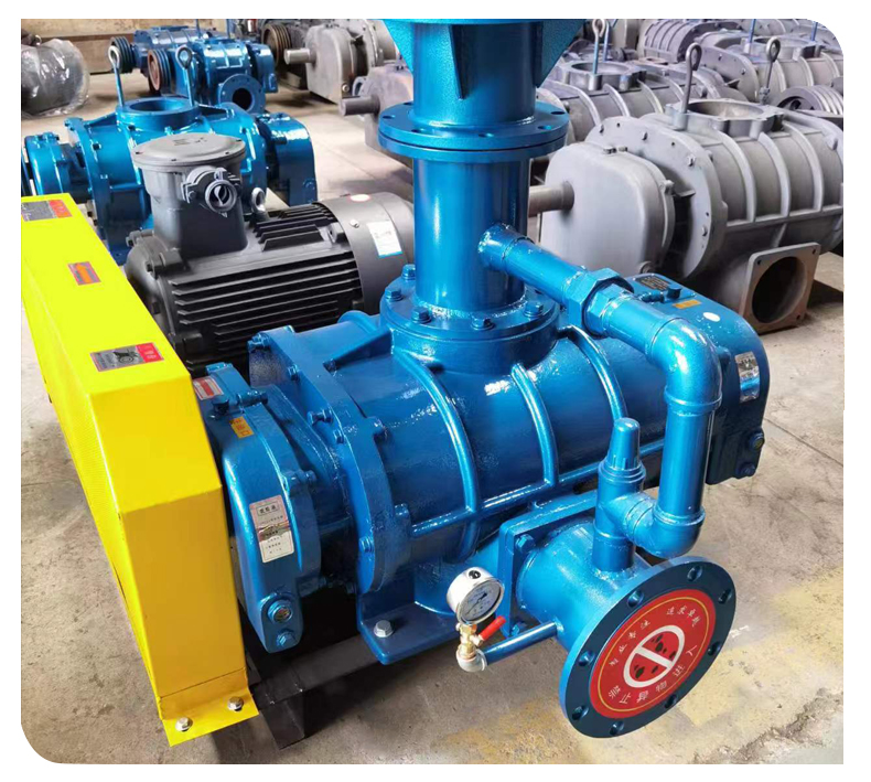
Principle: A small gap (usually 0.1-0.5mm) is formed between the rotor and the cylinder, and between the rotors. Gas is forcibly pushed from the intake port to the exhaust port by the rotor teeth. The flow rate is only related to the speed and geometric dimensions, and is independent of the outlet pressure.
Performance:
When the speed is constant and the system resistance is stable, the flow rate hardly changes with pressure (when the pressure fluctuates by ± 10%, the flow rate fluctuates by less than ± 1%).
Suitable for scenarios that require constant gas supply, such as sewage treatment aeration and pneumatic conveying.
Comparison: The flow rate of a centrifugal fan decreases with increasing pressure (the air volume pressure curve shows a decreasing trend), while the flow rate pressure curve of a Roots fan is a horizontal straight line. - External compression design, limited pressure ratio
Principle: Gas compression relies on the return of high-pressure gas from the exhaust port to the rotor teeth, forming “back pressure compression”, rather than the rotor directly doing work on the gas.
Performance:
Low single-stage pressure ratio: usually ≤ 1.7 (outlet pressure ≤ 1.5 times inlet pressure), with a maximum of only 2.1.
Difficulty in multi-stage series connection: Precise sealing is required between stages, otherwise gas leakage will cause a sudden drop in efficiency (actual multi-stage pressure ratio is usually less than 3.5).
Comparison: Screw compressors are designed for internal compression, with a single-stage pressure ratio of up to 3-5; Centrifugal compressor single-stage pressure ratio>2, multi-stage series connection can reach more than 50. - No internal compression process, high exhaust temperature
Principle: The gas is not compressed in the rotor slot and is only instantly compressed by high-pressure gas at the exhaust port, resulting in adiabatic compression and temperature rise.
Performance:
The exhaust temperature is usually 50-80 ℃ higher than the intake temperature (for example, when the intake temperature is 20 ℃, the exhaust temperature can reach 70-100 ℃).
If the intake temperature is too high (>40 ℃) or the pressure fluctuates greatly, the exhaust temperature may exceed 150 ℃, accelerating the oxidation of lubricating oil.
Response measures: A cooling system (such as air-cooled or water-cooled) should be configured, or high-temperature resistant lubricating oil should be selected. - Gap sealing, micro oil or oil-free design
Principle: The rotor and cylinder rely on a small gap to achieve sealing, requiring lubricating oil to reduce wear and form an oil film seal.
Performance:
Micro oil lubrication: Lubricating oil is discharged with gas (with an oil content of about 3-10 mg/m ³), and a subsequent oil separation device is required.
Oil free design: using self-lubricating materials (such as carbon rings, ceramics) or dry operation, but with high cost and short lifespan.
Comparison: Screw compressors achieve oil-free output through oil film sealing (requiring precise oil circuit control), while centrifugal fans do not require lubricating oil to come into contact with gas.
2、 Performance parameter characteristics - Flow range
Typical value: 0.5-500 m ³/min (small to large models).
Limitation: When the flow rate is ultra-low (<0.5 m ³/min), the geometric dimensions of the rotor are too small, which makes it difficult to process and reduces efficiency. - Pressure range
Typical value: 9.8-196 kPa (gauge pressure, i.e. 0.1-2.0 bar).
Limit: The maximum outlet pressure of a single stage is about 200 kPa, exceeding which multiple stages need to be connected in series (but in practical applications, the multi-stage pressure ratio is usually less than 3.5). - Efficiency characteristics
Peak efficiency: about 65-75% (lower than 75-85% for screw compressors and 80-90% for centrifugal compressors).
Efficiency curve: The efficiency is relatively high near the rated operating conditions, but significantly decreases when deviating from the design point (such as flow or pressure changes>± 20%). - Speed range
Typical value: 300-3000 rpm (small high-speed models can reach up to 5000 rpm).
Limitation: At low speeds (<50% rated speed), gas reflux can cause a sudden drop in efficiency; At high speeds, the inertia force of the rotor increases, and vibration and noise intensify.
3、 Characteristics of operational stability - Strong resistance to load fluctuations
Performance: When there is a sudden change in system resistance (such as pipeline blockage or valve closure), the Roots blower can avoid immediate shutdown by running under short-term overload (allowing for short-term overpressure of 10-20%).
Comparison: Centrifugal fans are prone to surge (rapid flow fluctuations) during sudden load changes and require anti surge control systems. - Sensitive to intake conditions
Dust: When the intake dust content is greater than 50 mg/m ³, dust will wear down the rotor and cylinder, shortening their lifespan.
Humidity: High humidity gases may cause lubricating oil emulsification, and a gas water separator needs to be configured.
Corrosivity: When containing corrosive gases (such as Cl ₂, H ₂ S), corrosion-resistant materials (such as stainless steel, Hastelloy alloy) should be selected. - Vibration and noise
Vibration: Poor rotor dynamic balance or uneven clearance can cause vibration, and regular calibration of dynamic balance is required.
Noise: The typical noise level is 85-95 dB (A), mainly from rotor engagement and gas backflow, requiring the installation of mufflers and soundproof covers.
4、 Maintenance and lifespan characteristics - Maintenance cycle
Lubricating oil replacement: Every 2000-5000 hours (depending on operating conditions), the oil quality (acid value, viscosity) needs to be tested.
Bearing replacement: Every 10000-20000 hours (rolling bearings), sliding bearings have a longer lifespan but require more precise maintenance.
Gap adjustment: Check the rotor gap every 5000-10000 hours. If the wear exceeds the limit, the rotor needs to be returned to the factory for repair or replacement. - Typical lifespan
Whole machine lifespan: 10-15 years (under good maintenance), but the lifespan of key components such as rotors and bearings is usually 5-8 years.
Factors affecting lifespan:
Operating temperature (50% reduction in lifespan for every 10 ℃ increase);
When the dust concentration exceeds 100 mg/m ³, the lifespan is halved;
Lubricating oil quality (poor quality oil leads to accelerated wear).