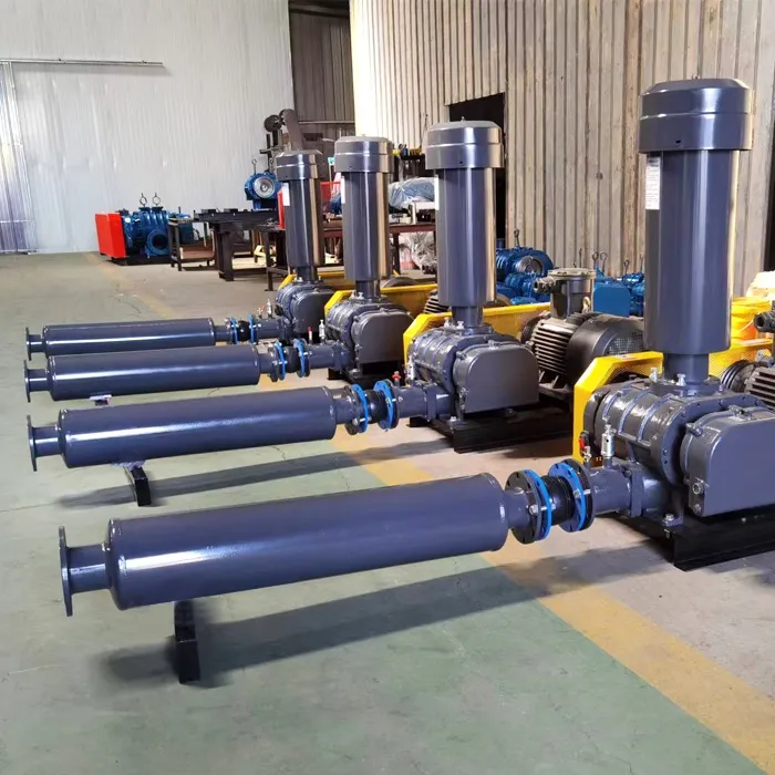
As a volumetric gas conveying equipment, the operational stability of Roots blower is directly related to the continuity, equipment life, and safety of the process system. Due to the precise clearance between the rotor and cylinder in Roots blower for gas delivery, its stability requirements cover multiple dimensions such as mechanical structure, airflow control, environmental adaptability, and long-term operational reliability. The following provides a detailed explanation from three aspects: core requirements, influencing factors, and safeguard measures:
1、 The core requirement for the stability of Roots blower operation
- Mechanical vibration control
Requirement: The vibration amplitude must be strictly controlled within the design range (usually ≤ 0.1mm) to avoid changes in the clearance between the rotor and cylinder, increased bearing wear, or loose pipeline connections caused by vibration.
Key points:
Rotor dynamic balancing: The rotor needs to undergo high-precision dynamic balancing correction (balance level G2.5 or higher) to ensure minimal centrifugal force during rotation.
Gap uniformity: The gaps between rotors and cylinders, as well as between rotors, should be consistent (with an error of ≤ 0.05mm) to prevent local friction or gas backflow.
Bearing stiffness: Select high rigidity bearings (such as double row tapered roller bearings) and ensure that the installation preload meets the design requirements to avoid axial displacement. - Suppression of airflow pulsation
Requirement: The fluctuation amplitude of exhaust airflow should be ≤ 5% of the rated flow rate to prevent pipeline vibration, instrument reading distortion, or process system loss of control caused by pressure fluctuations.
Key points:
Optimization of rotor tooth profile: Adopting involute or cycloidal tooth profile design to reduce impact and backflow during gas compression process.
Exhaust muffler: Install an impedance composite muffler at the exhaust outlet to reduce high-frequency noise and airflow pulsation (with a noise reduction of ≥ 20dB (A)).
Buffer tank configuration: A buffer tank (with a volume ≥ 10% of the fan flow) is installed at the outlet of the fan to balance pressure fluctuations and stabilize airflow output. - Temperature stability
Requirement: The operating temperature should be controlled within the design range (usually bearing temperature ≤ 80 ℃, exhaust temperature ≤ 100 ℃) to avoid high temperature causing lubricating oil oxidation, seal aging, or material deformation.
Key points:
Cooling system design: Choose air cooling or water cooling according to the working conditions to ensure that the heat dissipation efficiency meets the requirements (such as a cooling water flow rate of ≥ 5L/min in the water cooling system).
Lubricant selection: Choose synthetic lubricants with good high-temperature stability (such as PAO or polyether), and regularly check the oil quality (acid value, viscosity change ≤ 15%).
Intake temperature control: If the intake temperature is too high, it will exacerbate the exhaust temperature rise. It is necessary to configure an intake cooler or pre cooling device (the recommended intake temperature is ≤ 40 ℃). - Load adaptability
Requirement: When the system resistance fluctuates (such as pipeline blockage, valve opening changes), the fan needs to maintain stable operation to avoid surge or overload shutdown.
Key points:
Overload protection: Install motor overload protection devices (such as thermal relays or frequency converters) and set a reasonable overload current threshold (usually 1.2-1.5 times the rated current).
Pressure relief valve: Install a safety valve at the exhaust port to automatically release pressure when the pressure exceeds the set value (usually 1.1-1.2 times the rated pressure), preventing equipment damage.
Variable frequency speed regulation: By adjusting the speed through a frequency converter, the flow rate of the fan is dynamically matched with the system requirements, reducing the impact of sudden load changes on stability.
2、 Key factors affecting the stability of Roots blower - Mechanical factors
Rotor wear: After long-term operation, the wear of the rotor teeth will lead to an increase in clearance, causing gas reflux and intensified vibration.
Bearing failure: Insufficient lubrication or improper installation of the bearing can cause axial displacement and disrupt the uniformity of rotor clearance.
Coupling alignment: When the alignment error between the motor and fan coupling is greater than 0.05mm, it will cause additional vibration and bearing wear. - Airflow factors
Inlet dust: Dust particles (>50 μ m) will wear down the rotor surface and cylinder inner wall, causing changes in clearance and a decrease in efficiency.
Gas humidity: High humidity gases (relative humidity>80%) may cause lubricant emulsification and reduce lubrication effectiveness.
Gas corrosiveness: Corrosive gases (such as Cl ₂, H ₂ S) can corrode rotor materials and shorten equipment life. - Environmental factors
Installation foundation: Insufficient foundation stiffness or resonance frequency close to the operating frequency of the fan (usually 2-3 times the speed) will amplify vibration.
Power supply quality: Voltage fluctuations (>± 5%) or frequency deviations (>± 1%) can cause unstable motor speed and affect airflow output.
Temperature changes: Sudden changes in ambient temperature (such as not preheating before starting in winter) can cause uneven thermal expansion and contraction of the rotor, leading to changes in clearance.
3、 Measures to ensure the stability of Roots blower - Design and Manufacturing Stage
Optimizing rotor structure: Adopting a three bladed rotor design (reducing airflow pulsation by 30% compared to a two bladed rotor), and optimizing tooth profile parameters (such as tooth tip arc radius and tooth root fillet radius).
Precision machining and assembly: The machining accuracy of the rotor and cylinder needs to reach IT6 level, and a laser alignment instrument is used during assembly to ensure uniform clearance.
Enhanced cooling design: Water cooled models need to be equipped with independent circulating water circuits, while air-cooled models need to optimize the layout of heat sinks (heat dissipation area ≥ 0.5m ²/kW). - Installation and commissioning phase
Foundation reinforcement: A concrete foundation (with a mass ≥ 3 times the weight of the fan) is used, and shock-absorbing pads are installed (with a stiffness coefficient that matches the weight of the fan).
Pipeline design: avoid sharp bends or sudden changes in cross-section of the pipeline, and reduce airflow resistance; The recommended length of the exhaust pipe is ≤ 10m to reduce pressure loss.
Dynamic balance correction: Re perform rotor dynamic balance correction on site (especially for equipment after long-distance transportation) to eliminate the impact of transportation vibration. - Operation and maintenance phase
Regular inspection: Check vibration values (using a vibration analyzer), bearing temperature (infrared thermometer), and exhaust pressure (pressure gauge) for each shift, record data, and analyze trends.
Lubrication management: Replace lubricating oil every 2000-5000 hours and clean the oil circuit; Regularly sample and test the oil quality (replace immediately if the acid value is greater than 2mgKOH/g).
Gap adjustment: Check the rotor gap every 5000-10000 hours. If the wear exceeds the limit (such as gap>0.5mm), the rotor needs to be returned to the factory for repair or replacement.
Spare parts management: Reserve key spare parts (such as bearings, seals, rotors) to ensure quick replacement in case of failure and reduce downtime.
4、 Typical consequences and cases of insufficient stability - Excessive vibration leads to rotor fracture
Case: A Roots blower in a sewage treatment plant suffered from excessive coupling misalignment, resulting in rotor fracture after 3 months of operation, leading to equipment scrapping and process interruption.
Lesson: Strict alignment and regular re inspection (once every six months) must be carried out during installation. - High exhaust temperature causing fire
Case: A certain chemical enterprise’s Roots blower suffered significant losses due to high intake temperature (60 ℃) and cooling system failure, resulting in carbonization and ignition of lubricating oil.
Lesson: It is necessary to configure intake temperature monitoring and over temperature alarm devices, and regularly check the cooling system. - Pipeline rupture caused by airflow pulsation
Case: A Roots blower in a pneumatic conveying system caused a safety accident due to the failure to install a buffer tank, resulting in the cracking of pipeline welds and material leakage caused by exhaust pulsation.
Lesson: It is necessary to design the buffer tank capacity based on flow and pressure fluctuations, and regularly check the pipeline strength.
5、 Summary: Key control points for stability of Roots blower
Mechanical accuracy: rotor dynamic balance, clearance uniformity, and bearing stiffness are the core of vibration control.
Airflow management: tooth profile optimization, muffler configuration, and buffer tank design can suppress pulsation.
Temperature control: Cooling system, lubricant selection, and intake temperature monitoring are key to preventing high temperatures.
Load adaptation: Overload protection, pressure relief valve, and variable frequency speed regulation can cope with system fluctuations.
Maintenance system: Regular inspections, lubrication management, and gap adjustment are the guarantees for long-term stable operation.
By managing the entire lifecycle from design, installation, operation to maintenance, the operational stability of Roots blowers can be significantly improved, the failure rate can be reduced, and the equipment life can be extended, thereby ensuring the safe and efficient operation of the process system.